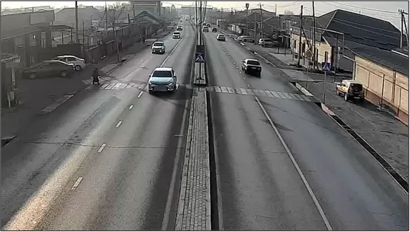
Right-of-Way Violations: Camera Installation Requirements
1. The detection of “Right-of-way” violations requires the installation of video cameras monitoring vehicle movement in braking zones, cameras monitoring pedestrian movement within the crosswalk zones, and overview cameras. Each function requires a corresponding type of video camera as listed in Table 1.
Table 1
| Function | Abbreviation |
| License plate recognition of vehicles and detection of vehicle movement through the crosswalk | LPR |
| Panoramic overview video camera | OV |
| Detection and tracking of pedestrian movement within a configured crosswalk zone | PED |
2. Cameras for license plate recognition (LPR) of the vehicles moving through the crosswalk.
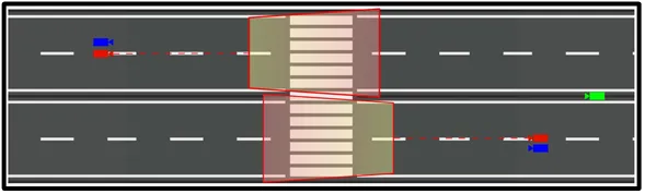
2.1. An example of LPR camera placement is shown in Figure 1 (red indicates the crosswalk zone).
Figure 1.
2.2. To generate traffic violation events, the LPR camera installation must comply with the requirements specified in Table 2.
Table 2
| Characteristic | Value |
| Tilt | from 10° to +30° |
| Pan | from –20° to +20° |
| Roll | from –5° to +5° |
| Image quality at the boundary of the controlled zone | 300 pixels/meter or higher |
| Illumination of the controlled zone (in the motion detection area for cameras without additional scene illumination) | 50 lx or higher across the entire camera scene |
| Recommended camera mounting height | 6 meters or higher above the road surface |
2.3 The following objects must be included within the LPR camera field of view:
- front license plates of vehicles;
- the pedestrian crossing across the full width of all traffic lanes. When using video cameras with a resolution of 2 megapixels (1920 × 1080 pixels), it is recommended to detect violations of the type “Failure to yield to pedestrians” at pedestrian crossings no wider than 5 meters;
- additional zones extending 3–5 meters before and after the pedestrian crossing in the direction of vehicle movement.
2.3.1. The mounting height of LPR cameras should be as high as possible (within the limits specified in Table 2).
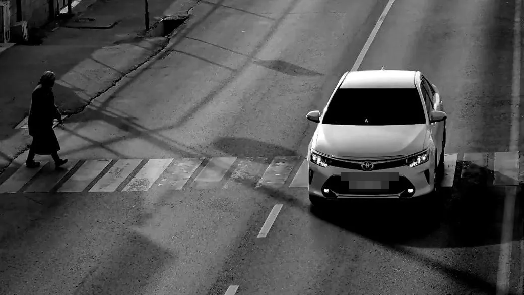
2.4. Examples of images obtained from LPR cameras are shown in Figure 2.
Figure 2
3. Cameras for pedestrian detection (PED).
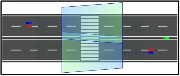
3.1. An example of the layout and coverage zones of PED cameras on a road section with a crosswalk zone (shown in blue) for detecting the presence of pedestrians within the crosswalk is presented in Figure 3.
Figure 3
3.2. To generate traffic violation events of the type “Failure to yield to pedestrians,” the installation of PED cameras must comply with the requirements specified in Table 3.
Table 3
| Characteristic | Value |
| Tilt | from +10° to +45° |
| Pan | from –30° to +30° |
| Roll | from –5° to +5° |
| Image quality at the boundary of the controlled zone | 50 pixels/meter or higher |
| Illumination of the controlled zone (in the motion detection area for cameras without additional scene illumination) | 10 lx or higher |
| Recommended camera mounting height | 5 meters or higher above the road surface |
3.3. Recommendations for selecting and configuring the PED camera field of view
The following objects must be included within the PED camera field of view:
- the entire crosswalk area for one controlled direction of vehicle movement. When using video cameras with a resolution of 2 megapixels (1920 × 1080 pixels), it is recommended to detect violations of the type “Failure to yield to pedestrians” at pedestrian crossings with a length of up to four traffic lanes in one direction;
- additional zones extending 8–10 meters before and after the crosswalk in the direction of vehicle movement (within the limits specified in Table 3);
- additional zones extending 1–2 meters to the right and left of the crosswalk, with the minimum possible pan and tilt (within the limits specified in Table 3).
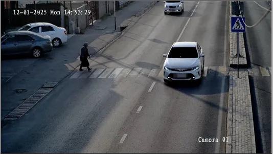
3.3.1. To ensure higher-quality evidentiary images of recorded violations of the type “Failure to yield to pedestrians,” it is recommended to use video cameras that operate continuously in color mode and are equipped with visible-spectrum illumination (for example, Hikvision ColorVu or Dahua Full Color).
3.4. Examples of images obtained from PED cameras in the pedestrian crossing zone are shown in Figure 4.
Figure 4
4. Additional overview video cameras (hereinafter – OV cameras)
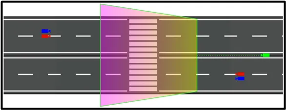
Additional overview video cameras are used to expand the field of view and to capture violations from an alternative observation angle.
4.1. An example of the layout and coverage zones of OV cameras on a road section with a crosswalk area (shown in green) is presented in Figure 5.
Figure 5
4.2. To generate traffic violation events of the type “Failure to yield to pedestrians,” the installation of OV cameras must comply with the requirements specified in Table 4.
Table 4
| Characteristic | Value |
| Tilt | from +15° to +75° |
| Pan | from –75° to +75° |
| Roll | from –5° to +5° |
| Image quality at the boundary of the controlled zone | 50 pixels/meter or higher |
| Illumination of the controlled zone (in the motion detection area for cameras without additional scene illumination) | 10 lx or higher |
| Recommended camera mounting height | 5 meters or higher above the road surface |
4.3. Recommendations for selecting and configuring the OV camera field of view
The following objects must be included within the OV camera field of view:
- the entire area of the controlled pedestrian crosswalk;
- additional zones extending 8–10 meters before and after the pedestrian crosswalk in the direction of vehicle movement (within the limits specified in Table 4);
- additional zones extending 1–2 meters to the right and left of the pedestrian crosswalk (within the limits specified in Table 4).
4.4. Examples of images obtained from OV cameras in the pedestrian crossing zone are shown in Figure 6.
Figure 6.