
Forbidden Maneuver Violations: Camera Installation Requirements
1. The detection of a “Forbidden maneuver” violation requires the installation of video cameras monitoring entry to the intersection/start of maneuver, exit from the intersection/end of maneuver, and overview cameras. Each application function requires a corresponding type of video camera as listed in Table 1.
Table 1
| Camera function | Abbreviation |
| License plate recognition of vehicles at the entry to the controlled road section. Detection of crossing a virtual line | LPR |
| License plate recognition of vehicles at the exit from the controlled road section. Detection of crossing a virtual line | LPR |
| Panoramic overview video camera | OV |
2. To generate traffic violation events, LPR installation must comply with the requirements specified in Table 2.
Table 2
| Characteristic | Requirement |
| Tilt | from 10° to +30° |
| Pan | from –20° to +20° |
| Roll | from –5° to +5° |
| Image quality at the boundary of the controlled zone | 300 pixels/meter or higher |
| Illumination of the controlled zone | 50 lx or higher across the entire scene |
| Camera mounting height | From 6 meters or higher above the road surface |
3. To obtain additional data for evidence generation and better identification of secondary vehicle features, including at night, OV installation must comply with Table 3.
Table 3
| Characteristic | Requirement |
| Tilt | from +15° to +75° |
| Pan | from –75° to +75° |
| Roll | from –5° to +5° |
| Image quality | 50 pixels/meter or higher |
| Illumination | 10 lx or higher |
| Mounting height | 5 meters or higher |
4. Camera placement for maneuver control at intersections.
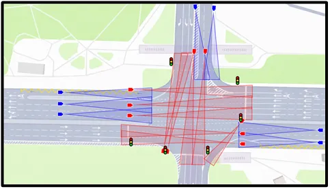
4.1. Example LPR placement is shown in Figure 1 (red indicates entry cameras, blue indicates exit cameras).
Figure 1.
4.2. LPR field-of-view recommendations:
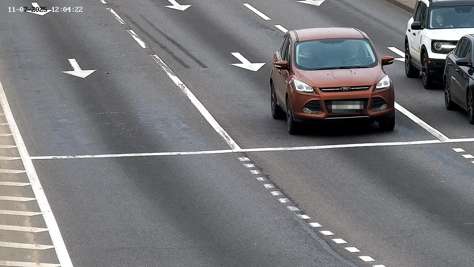
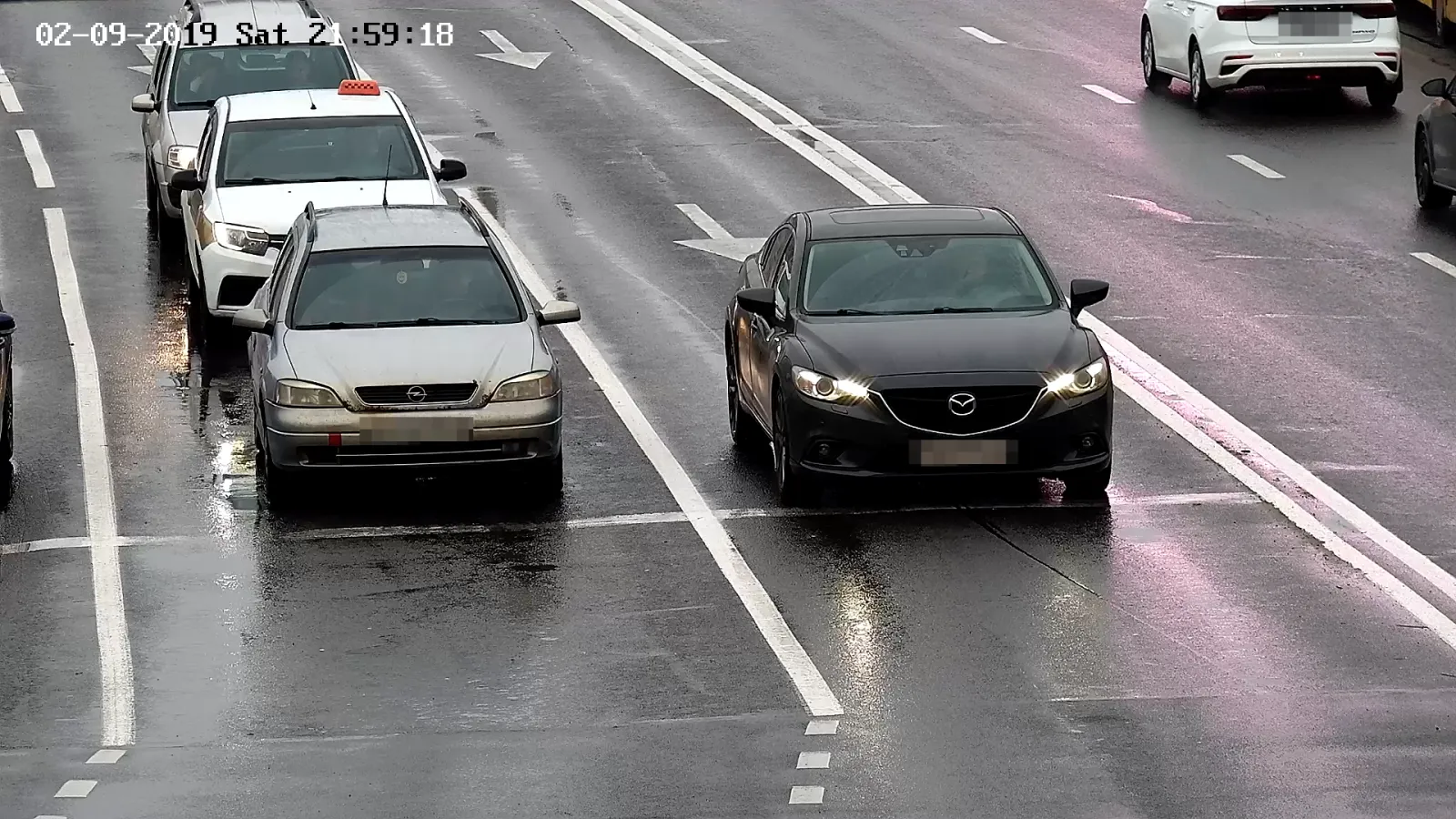
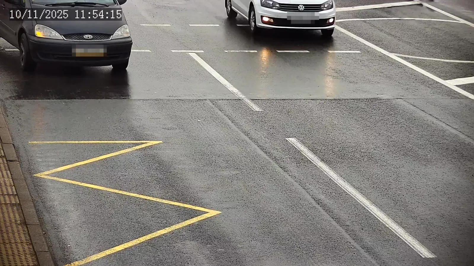
- Cameras must capture front license plates.
- Entry cameras must also capture the stop line (if present), located in the second third of the frame horizontally.
- Exit cameras must include the intersection area in the upper part of the image.
- Cameras should be installed as high as possible within the limits specified in Table 2.
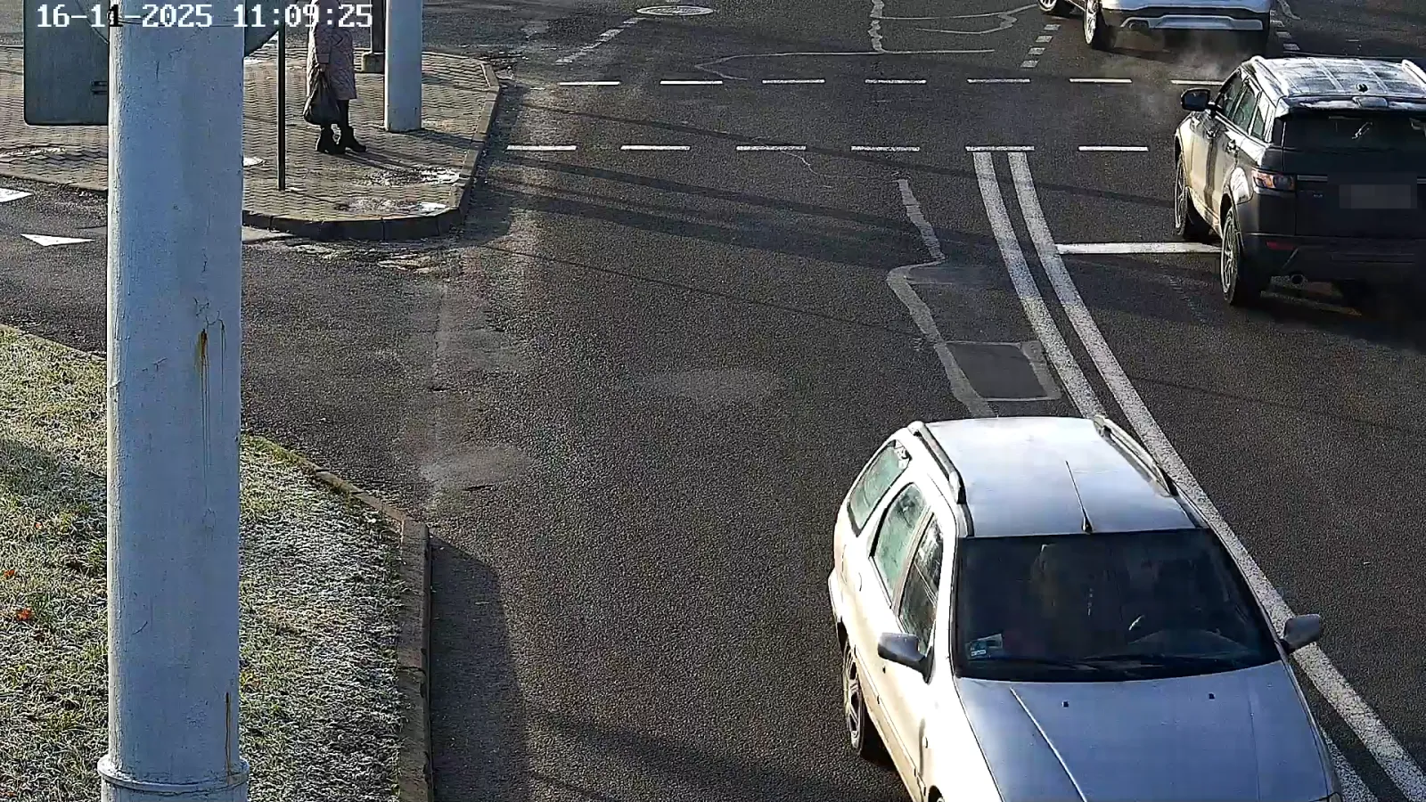
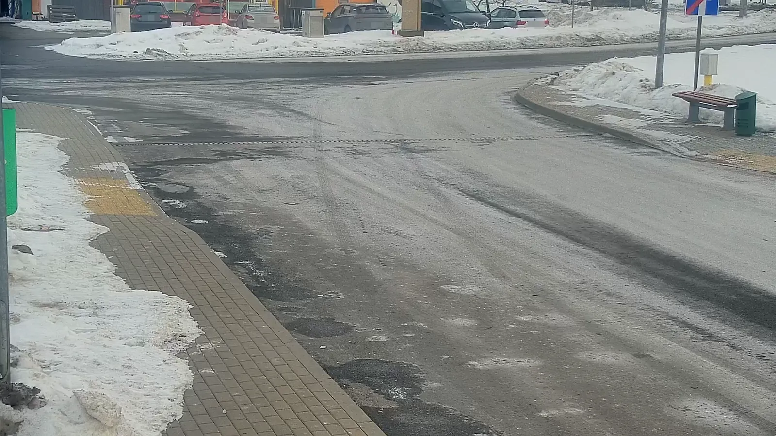
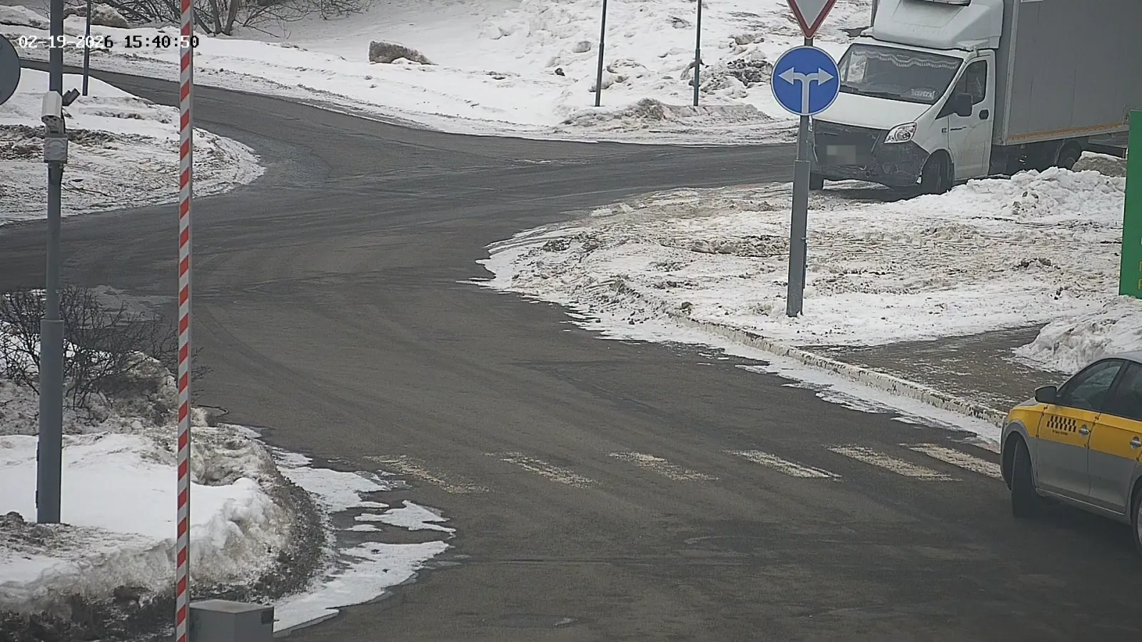
- Figure 2 shows the example images from LPR cameras (red indicates OV cameras overviewing the entry, blue - the exit).
Figure 2.
 |  |
 |  |
 |  |
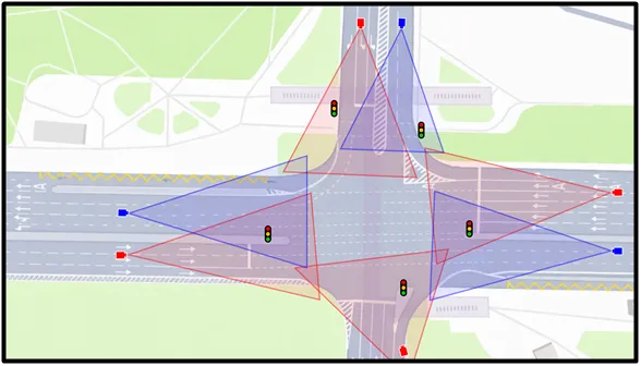
4.4. Example OV placement is shown in Figure 3 (red indicates OV cameras overviewing the entry, blue - the exit).
Figure 3.
4.5. OV field-of-view recommendations:
- Entry cameras must capture the entry line and at least 8 m before and after it.
- Exit cameras must capture the exit line and at least 15 m before it.
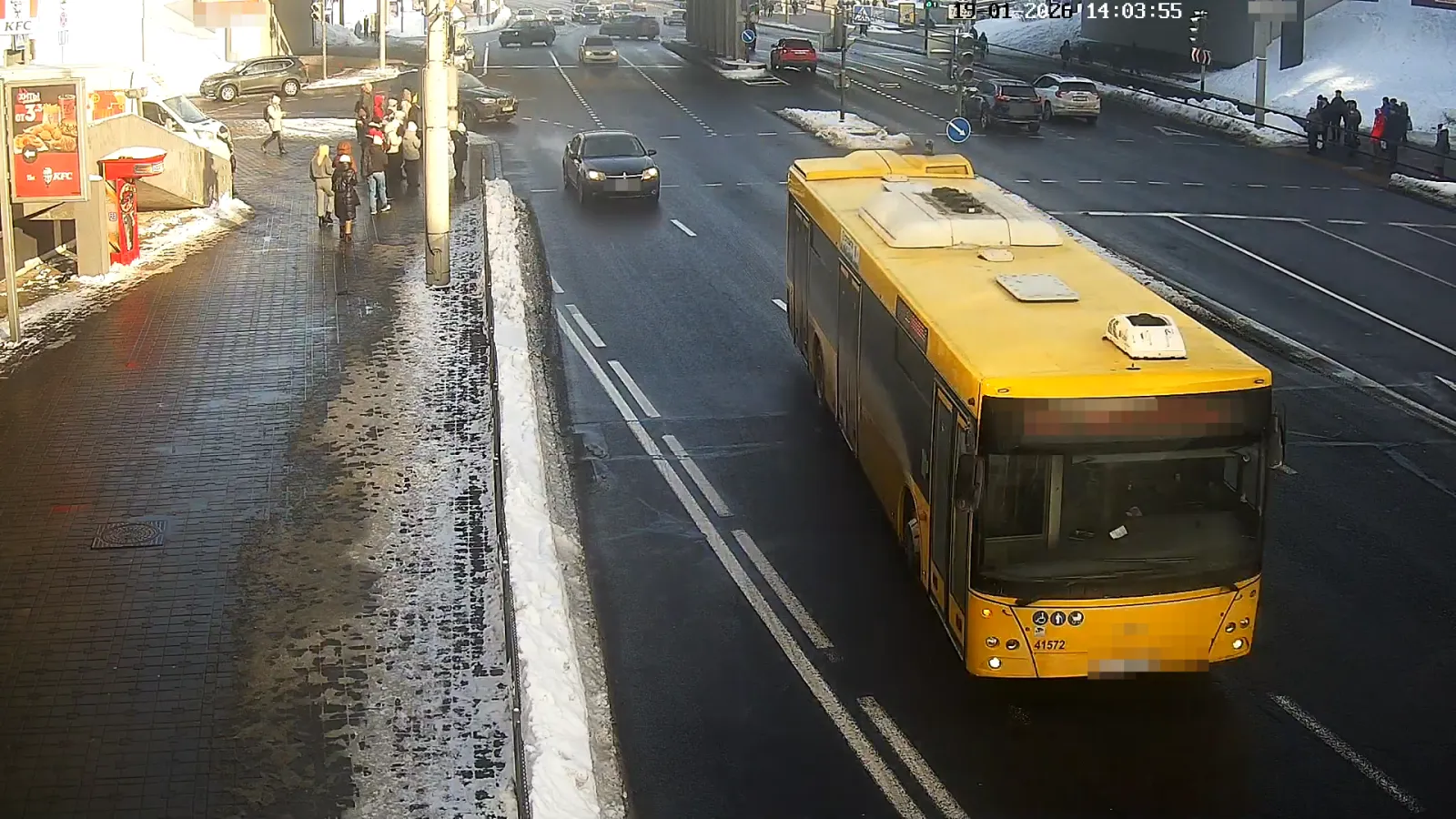
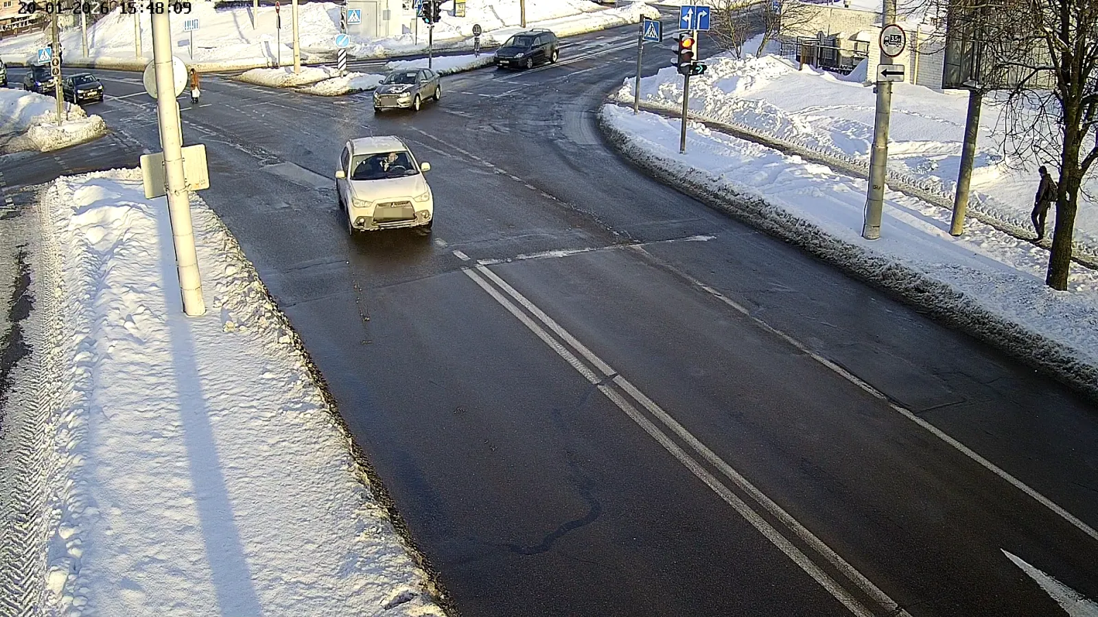
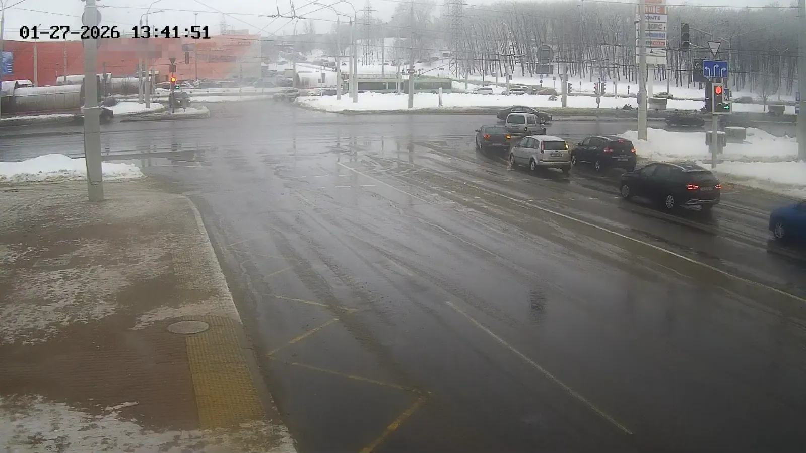
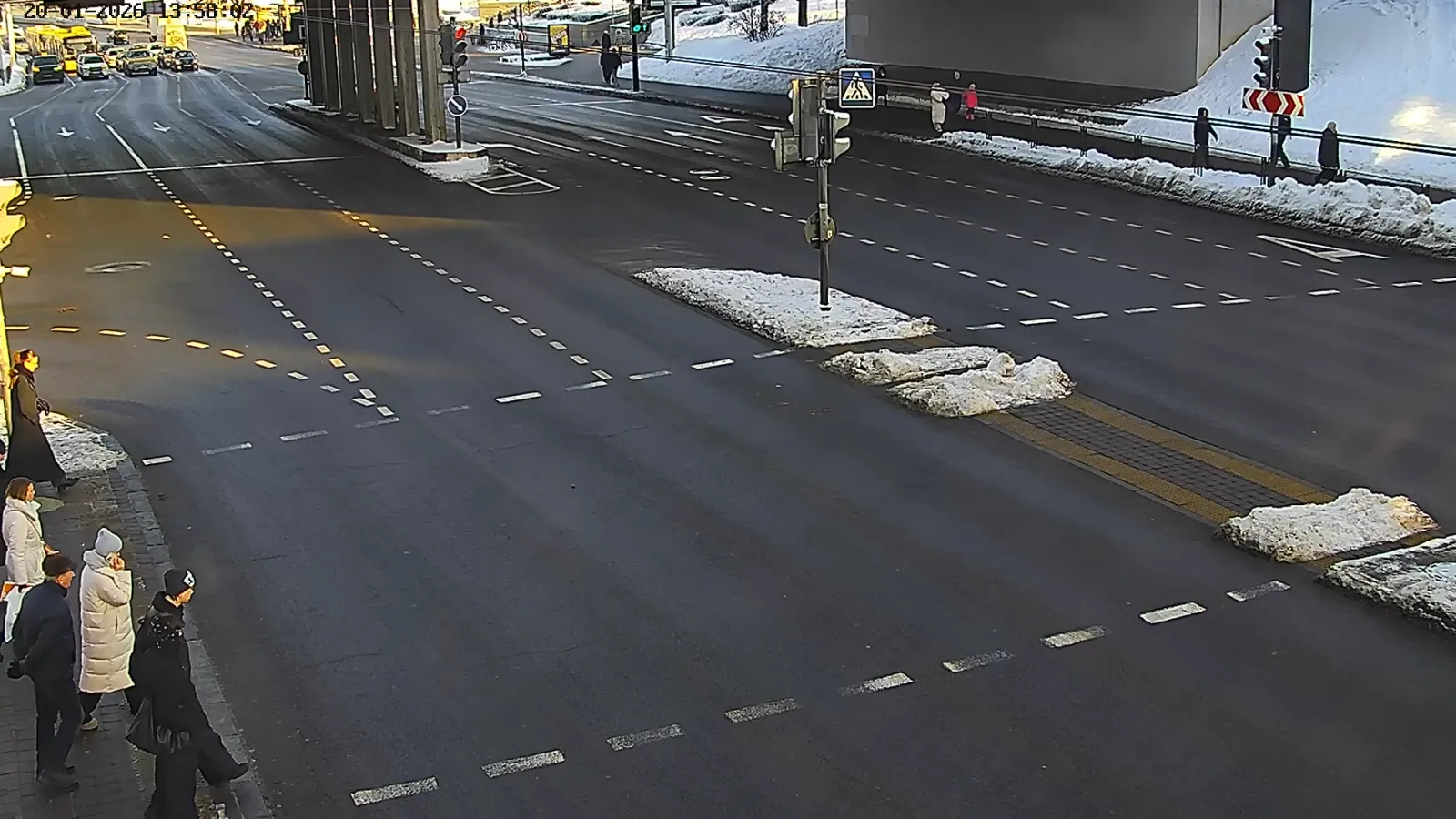
4.6 Figure 4 shows the example images from OV cameras.
Figure 4
 |  |
 |  |