
Railway Crossing Violations: Camera Installation Requirements
1. Detection of “Railway crossing” violations requires the installation of video cameras monitoring entry to the railway crossing, exit from the railway crossing, cameras detecting railway signal lights, and overview cameras. Each function requires a corresponding type of video camera as listed in Table 1.
Table 1
| Camera function | Abbreviation |
| License plate recognition of vehicles entering the railway crossing. Detection of crossing a virtual line (stop line) | LPR |
| License plate recognition of vehicles leaving the railway crossing. Detection of crossing a virtual line | LPR |
| Railway signal detection | TL |
| Panoramic overview video camera | OV |
2. Cameras for license plate recognition at the entry and exit of the railway crossing (LPR).
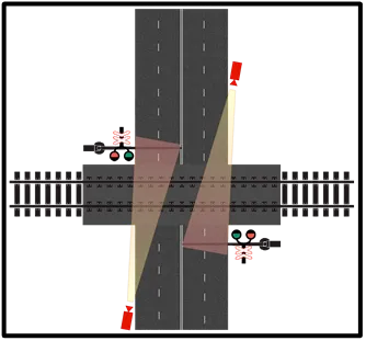
2.1. An example of LPR placement is shown in Figure 1 (red indicates entry cameras, blue indicates exit cameras).
Figure 1.
2.2. LPR installation must comply with Table 2 requirements.
Table 2
| Characteristic | Requirement |
| Tilt | from 10° to +30° |
| Pan | from –20° to +20° |
| Roll | from –5° to +5° |
| Image quality | 300 pixels/meter or higher |
| Illumination | 50 lx or higher |
| Mounting height | From 6 meters ot higher above the road surface. The highest possible mounting height is recommended to reduce vehicle occlusion. |
2.3. LPR field-of-view recommendations:
- Cameras must capture front license plates.
- Entry cameras must include the stop line (if present), located in the second third of the frame horizontally.
- Exit cameras must include the crossing area in the upper part of the image.
- Cameras should be installed as high as possible within the limits specified in Table 2.
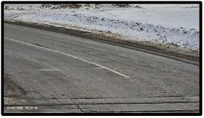
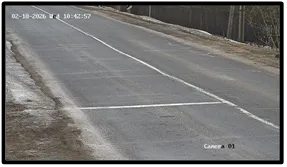
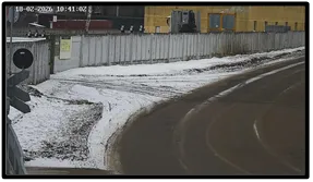
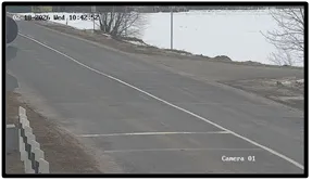
- Figure 2 below shows the example images from the entry and exit cameras
Figure 2.
 |  |
 |  |
3. Cameras for railway signal detection (TL).
3.1. Example placement is shown in Figure 3.
Figure 3.
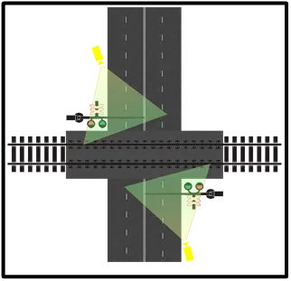
3.2. TL installation must comply with Table 3.
Table 3
| Characteristic | Requirement |
| Tilt | from +5° to +30° |
| Pan | from –45° to +45° |
| Roll | from –5° to +5° |
| Image quality | 150 pixels/meter or higher |
| Illumination | 10 lx or higher |
| Mounting height | 6 meters or higher |
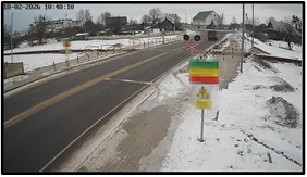
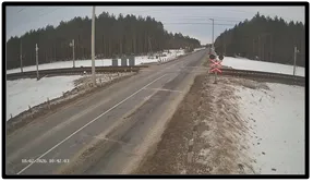
3.3. TL field-of-view recommendations:
- Install on the same side as the railway signal.
- Mount 1–2 meters higher than the signal.
- Cover at least 15 meters before the stop line.
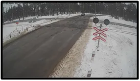
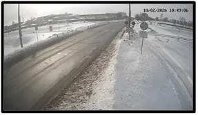
Figure 4 shows the example images from TL cameras.
Figure 4.
 |  |
 |  |
4. Overview cameras (OV) for general monitoring and evidence collection.
4.1. Example placement is shown in Figure 5.
Figure 5.
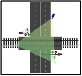
4.2. OV installation must comply with Table 4.
| Characteristic | Requirement |
| Tilt | from +15° to +75° |
| Pan | from –75° to +75° |
| Roll | from –5° to +5° |
| Image quality | 50 pixels/meter or higher |
| Illumination | 10 lx or higher |
| Mounting height | 5 meters or higher |
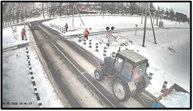
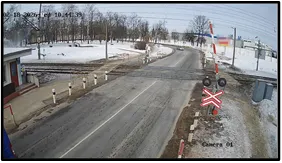
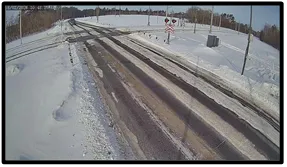
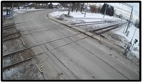
4.3. OV field-of-view recommendations:
- Mount cameras as high as possible.
- Place diagonally to reduce occlusion.
- Figure 6 shows the example images from OV cameras.
Figure 6.
 |  |
 |  |